Product Description
Flexible flex Fluid Chain Jaw flange Gear Rigid Spacer PIN HRC MH NM universal Fenaflex Oldham spline clamp tyre grid hydraulic servo motor shaft Coupling
Product Description
The function of Shaft coupling:
1. Shafts for connecting separately manufactured units such as motors and generators.
2. If any axis is misaligned.
3. Provides mechanical flexibility.
4. Absorb the transmission of impact load.
5. Prevent overload
We can provide the following couplings.
| Rigid coupling | Flange coupling | Oldham coupling |
| Sleeve or muff coupling | Gear coupling | Bellow coupling |
| Split muff coupling | Flexible coupling | Fluid coupling |
| Clamp or split-muff or compression coupling | Universal coupling | Variable speed coupling |
| Bushed pin-type coupling | Diaphragm coupling | Constant speed coupling |
Company Profile
We are an industrial company specializing in the production of couplings. It has 3 branches: steel casting, forging, and heat treatment. Main products: cross shaft universal coupling, drum gear coupling, non-metallic elastic element coupling, rigid coupling, etc.
The company mainly produces the industry standard JB3241-91 swap JB5513-91 swc. JB3242-93 swz series universal coupling with spider type. It can also design and produce various non-standard universal couplings, other couplings, and mechanical products for users according to special requirements. Currently, the products are mainly sold to major steel companies at home and abroad, the metallurgical steel rolling industry, and leading engine manufacturers, with an annual production capacity of more than 7000 sets.
The company’s quality policy is “quality for survival, variety for development.” In August 2000, the national quality system certification authority audited that its quality assurance system met the requirements of GB/T19002-1994 IDT ISO9002:1994 and obtained the quality system certification certificate with the registration number 0900B5711. It is the first enterprise in the coupling production industry in HangZhou City that passed the ISO9002 quality and constitution certification.
The company pursues the business purpose of “reliable quality, the supremacy of reputation, commitment to business and customer satisfaction” and welcomes customers at home and abroad to choose our products.
At the same time, the company has established long-term cooperative relations with many enterprises and warmly welcomes friends from all walks of life to visit, investigate and negotiate business!
How to use the coupling safely
The coupling is an intermediate connecting part of each motion mechanism, which directly impacts the regular operation of each motion mechanism. Therefore, attention must be paid to:
1. The coupling is not allowed to have more than the specified axis deflection and radial displacement so as not to affect its transmission performance.
2. The bolts of the LINS coupling shall not be loose or damaged.
3. Gear coupling and cross slide coupling shall be lubricated regularly, and lubricating grease shall be added every 2-3 months to avoid severe wear of gear teeth and serious consequences.
4. The tooth width contact length of gear coupling shall not be less than 70%; Its axial displacement shall not be more significant than 5mm
5. The coupling is not allowed to have cracks. If there are cracks, it needs to be replaced (they can be knocked with a small hammer and judged according to the sound).
6. The keys of LINS coupling shall be closely matched and shall not be loosened.
7. The tooth thickness of the gear coupling is worn. When the lifting mechanism exceeds 15% of the original tooth thickness, the operating mechanism exceeds 25%, and the broken tooth is also scrapped.
8. If the elastic ring of the pin coupling and the sealing ring of the gear coupling is damaged or aged, they should be replaced in time.
Certifications
Packaging & Shipping
/* January 22, 2571 19:08:37 */!function(){function s(e,r){var a,o={};try{e&&e.split(“,”).forEach(function(e,t){e&&(a=e.match(/(.*?):(.*)$/))&&1
| Standard Or Nonstandard: | Nonstandard |
|---|---|
| Shaft Hole: | 19-32 |
| Torque: | <10N.M |
| Bore Diameter: | 19mm |
| Speed: | 8000r/M |
| Structure: | Rigid |
| Samples: |
US$ 999/Piece
1 Piece(Min.Order) | |
|---|
What are the maintenance requirements for flexible couplings?
Maintenance of flexible couplings is essential to ensure their reliable and efficient performance over their service life. Proper maintenance helps prevent premature wear, reduces the risk of unexpected failures, and extends the lifespan of the couplings. Here are some key maintenance requirements for flexible couplings:
- Regular Inspection: Perform regular visual inspections of the flexible couplings to check for signs of wear, damage, or misalignment. Look for cracks, tears, or any other visible issues in the coupling components.
- Lubrication: Some flexible couplings, especially those with moving parts or sliding surfaces, may require periodic lubrication. Follow the manufacturer’s recommendations regarding the type and frequency of lubrication to ensure smooth operation.
- Alignment Checks: Misalignment is a common cause of coupling failure. Regularly check the alignment of the connected shafts and adjust as necessary. Proper alignment reduces stress on the coupling and improves power transmission efficiency.
- Torque Monitoring: Monitoring the torque transmitted through the coupling can help detect any abnormal or excessive loads. If the coupling is subjected to loads beyond its rated capacity, it may lead to premature failure.
- Environmental Protection: If the couplings are exposed to harsh environmental conditions, take measures to protect them from dust, dirt, moisture, and corrosive substances. Consider using protective covers or seals to shield the couplings from potential contaminants.
- Temperature Considerations: Ensure that the operating temperature of the flexible coupling is within its designed range. Excessive heat can accelerate wear, while extremely low temperatures may affect the flexibility of certain coupling materials.
- Replace Worn or Damaged Parts: If any components of the flexible coupling show signs of wear or damage, replace them promptly with genuine replacement parts from the manufacturer.
- Manufacturer’s Guidelines: Follow the maintenance guidelines provided by the coupling manufacturer. They often include specific maintenance intervals and procedures tailored to the coupling’s design and materials.
- Training and Expertise: Ensure that maintenance personnel have the necessary training and expertise to inspect and maintain the flexible couplings properly. Improper maintenance practices can lead to further issues and compromise the coupling’s performance.
By adhering to these maintenance requirements, you can maximize the service life of the flexible couplings and minimize the risk of unexpected downtime or costly repairs. Regular maintenance helps maintain the efficiency and reliability of the coupling in various industrial, automotive, and machinery applications.
Can flexible couplings be used in applications with varying operating temperatures?
Yes, flexible couplings can be used in applications with varying operating temperatures. The suitability of a flexible coupling for a specific temperature range depends on its design and the materials used in its construction. Different types of flexible couplings are available to handle a wide range of temperature conditions, making them versatile for use in various industries and environments.
High-Temperature Applications:
For applications with high operating temperatures, such as those found in certain industrial processes, exhaust systems, or high-temperature machinery, flexible couplings made from materials with excellent heat resistance are used. These materials may include stainless steel alloys, heat-treated steels, or specialized high-temperature elastomers. High-temperature flexible couplings are designed to maintain their mechanical properties, including flexibility and torque transmission capabilities, even at elevated temperatures.
Low-Temperature Applications:
Conversely, for applications in extremely cold environments or cryogenic processes, flexible couplings constructed from materials with low-temperature resistance are employed. These couplings are designed to remain flexible and functional at very low temperatures without becoming brittle or losing their ability to handle misalignment. Some low-temperature couplings may use special polymers or elastomers with excellent cold-temperature performance.
Temperature Range Considerations:
When selecting a flexible coupling for applications with varying operating temperatures, it is essential to consider the specific temperature range in which the coupling will operate. Some flexible couplings have a wider temperature range, allowing them to function effectively in both high and low-temperature environments. However, in extreme temperature conditions, specialized couplings may be necessary to ensure reliable performance and prevent premature failure.
Manufacturer Guidelines:
Manufacturers of flexible couplings provide guidelines and specifications regarding the temperature range of their products. It is crucial to consult the manufacturer’s documentation to ensure that the chosen coupling is suitable for the intended operating temperature of the application. Using a coupling beyond its recommended temperature range can lead to performance issues, reduced efficiency, or even failure.
Applications:
Flexible couplings with varying temperature resistance find use in numerous industries, including aerospace, automotive, manufacturing, power generation, and more. Whether in high-temperature exhaust systems, low-temperature cryogenic processes, or regular industrial applications with temperature fluctuations, flexible couplings play a vital role in providing reliable power transmission and misalignment compensation.
In summary, flexible couplings can be effectively used in applications with varying operating temperatures, provided that the coupling’s design and material properties align with the specific temperature requirements of the application.
What are the advantages of using flexible couplings in mechanical systems?
Flexible couplings offer several advantages in mechanical systems, making them essential components in various applications. Here are the key advantages of using flexible couplings:
- Misalignment Compensation: One of the primary advantages of flexible couplings is their ability to compensate for shaft misalignment. In mechanical systems, misalignment can occur due to various factors such as installation errors, thermal expansion, or shaft deflection. Flexible couplings can accommodate angular, parallel, and axial misalignment, ensuring smooth power transmission and reducing stress on the connected equipment and shafts.
- Vibration Damping: Flexible couplings act as damping elements, absorbing and dissipating vibrations and shocks generated during operation. This feature helps to reduce noise, protect the equipment from excessive wear, and enhance overall system reliability and performance.
- Torsional Flexibility: Flexible couplings provide torsional flexibility, allowing them to handle slight angular and axial deflections. This capability protects the equipment from sudden torque fluctuations, shock loads, and torque spikes, ensuring smoother operation and preventing damage to the machinery.
- Overload Protection: In case of sudden overloads or torque spikes, flexible couplings can absorb and distribute the excess torque, protecting the connected equipment and drivetrain from damage. This overload protection feature prevents unexpected failures and reduces downtime in critical applications.
- Reduce Wear and Maintenance: By compensating for misalignment and damping vibrations, flexible couplings help reduce wear on the connected equipment, bearings, and seals. This results in extended component life and reduced maintenance requirements, leading to cost savings and improved system reliability.
- Compensation for Thermal Expansion: In systems exposed to temperature variations, flexible couplings can compensate for thermal expansion and contraction, maintaining proper alignment and preventing binding or excessive stress on the equipment during temperature changes.
- Electric Isolation: Some types of flexible couplings, such as disc couplings, offer electrical isolation between shafts. This feature is beneficial in applications where galvanic corrosion or electrical interference between connected components needs to be minimized.
- Space and Weight Savings: Flexible couplings often have compact designs and low inertia, which is advantageous in applications with space constraints and where minimizing weight is crucial for performance and efficiency.
- Cost-Effectiveness: Flexible couplings are generally cost-effective solutions for power transmission and motion control, especially when compared to more complex and expensive coupling types. Their relatively simple design and ease of installation contribute to cost savings.
In summary, flexible couplings play a vital role in mechanical systems by providing misalignment compensation, vibration damping, overload protection, and torsional flexibility. These advantages lead to improved system performance, reduced wear and maintenance, and enhanced equipment reliability, making flexible couplings a preferred choice in various industrial, automotive, marine, and aerospace applications.


editor by CX 2024-04-19
China Custom Flexible Flex Fluid Chain Jaw Flange Gear Rigid Spacer Pin HRC Mh Nm Universal Fenaflex Oldham Spline Clamp Tyre Grid Hydraulic Servo Motor Shaft Coupling
Product Description
Flexible flex Fluid Chain Jaw flange Gear Rigid Spacer PIN HRC MH NM universal Fenaflex Oldham spline clamp tyre grid hydraulic servo motor shaft Coupling
Product Description
The function of Shaft coupling:
1. Shafts for connecting separately manufactured units such as motors and generators.
2. If any axis is misaligned.
3. Provides mechanical flexibility.
4. Absorb the transmission of impact load.
5. Prevent overload
We can provide the following couplings.
| Rigid coupling | Flange coupling | Oldham coupling |
| Sleeve or muff coupling | Gear coupling | Bellow coupling |
| Split muff coupling | Flexible coupling | Fluid coupling |
| Clamp or split-muff or compression coupling | Universal coupling | Variable speed coupling |
| Bushed pin-type coupling | Diaphragm coupling | Constant speed coupling |
Company Profile
We are an industrial company specializing in the production of couplings. It has 3 branches: steel casting, forging, and heat treatment. Main products: cross shaft universal coupling, drum gear coupling, non-metallic elastic element coupling, rigid coupling, etc.
The company mainly produces the industry standard JB3241-91 swap JB5513-91 swc. JB3242-93 swz series universal coupling with spider type. It can also design and produce various non-standard universal couplings, other couplings, and mechanical products for users according to special requirements. Currently, the products are mainly sold to major steel companies at home and abroad, the metallurgical steel rolling industry, and leading engine manufacturers, with an annual production capacity of more than 7000 sets.
The company’s quality policy is “quality for survival, variety for development.” In August 2000, the national quality system certification authority audited that its quality assurance system met the requirements of GB/T19002-1994 IDT ISO9002:1994 and obtained the quality system certification certificate with the registration number 0900B5711. It is the first enterprise in the coupling production industry in HangZhou City that passed the ISO9002 quality and constitution certification.
The company pursues the business purpose of “reliable quality, the supremacy of reputation, commitment to business and customer satisfaction” and welcomes customers at home and abroad to choose our products.
At the same time, the company has established long-term cooperative relations with many enterprises and warmly welcomes friends from all walks of life to visit, investigate and negotiate business!
How to use the coupling safely
The coupling is an intermediate connecting part of each motion mechanism, which directly impacts the regular operation of each motion mechanism. Therefore, attention must be paid to:
1. The coupling is not allowed to have more than the specified axis deflection and radial displacement so as not to affect its transmission performance.
2. The bolts of the LINS coupling shall not be loose or damaged.
3. Gear coupling and cross slide coupling shall be lubricated regularly, and lubricating grease shall be added every 2-3 months to avoid severe wear of gear teeth and serious consequences.
4. The tooth width contact length of gear coupling shall not be less than 70%; Its axial displacement shall not be more significant than 5mm
5. The coupling is not allowed to have cracks. If there are cracks, it needs to be replaced (they can be knocked with a small hammer and judged according to the sound).
6. The keys of LINS coupling shall be closely matched and shall not be loosened.
7. The tooth thickness of the gear coupling is worn. When the lifting mechanism exceeds 15% of the original tooth thickness, the operating mechanism exceeds 25%, and the broken tooth is also scrapped.
8. If the elastic ring of the pin coupling and the sealing ring of the gear coupling is damaged or aged, they should be replaced in time.
Certifications
Packaging & Shipping
/* January 22, 2571 19:08:37 */!function(){function s(e,r){var a,o={};try{e&&e.split(“,”).forEach(function(e,t){e&&(a=e.match(/(.*?):(.*)$/))&&1
| Standard Or Nonstandard: | Nonstandard |
|---|---|
| Shaft Hole: | 19-32 |
| Torque: | <10N.M |
| Bore Diameter: | 19mm |
| Speed: | 8000r/M |
| Structure: | Rigid |
| Samples: |
US$ 999/Piece
1 Piece(Min.Order) | |
|---|
Can flexible couplings be used in both horizontal and vertical shaft arrangements?
Yes, flexible couplings can be used in both horizontal and vertical shaft arrangements. The design of flexible couplings allows them to accommodate misalignment and compensate for angular, parallel, and axial displacements between the shafts, making them suitable for various shaft orientations.
Horizontal Shaft Arrangements:
In horizontal shaft arrangements, where the shafts are parallel to the ground or horizontal plane, flexible couplings are commonly used to connect two rotating shafts. These couplings help transmit torque from one shaft to another while accommodating any misalignment that may occur during operation. Horizontal shaft arrangements are common in applications such as pumps, compressors, conveyors, and industrial machinery.
Vertical Shaft Arrangements:
In vertical shaft arrangements, where the shafts are perpendicular to the ground or vertical plane, flexible couplings are also applicable. Vertical shafts often require couplings that can handle the additional weight and forces resulting from gravity. Flexible couplings designed for vertical applications can support the weight of the rotating equipment while allowing for some axial movement to accommodate thermal expansion or other displacements. Vertical shaft arrangements are commonly found in applications such as pumps, gearboxes, turbines, and some marine propulsion systems.
Considerations for Vertical Shaft Arrangements:
When using flexible couplings in vertical shaft arrangements, there are a few additional considerations to keep in mind:
- Thrust Load: Vertical shafts can generate thrust loads, especially in upward or downward direction. The flexible coupling should be selected based on its capacity to handle both radial and axial loads to accommodate these forces.
- Lubrication: Some vertical couplings may require additional lubrication to ensure smooth operation and reduce wear, particularly if they are exposed to high axial loads or extended vertical shafts.
- Support and Bearing: Proper support and bearing arrangements for the vertical shaft are essential to prevent excessive shaft deflection and ensure the flexible coupling functions correctly.
Overall, flexible couplings are versatile and adaptable to various shaft orientations, providing efficient power transmission and misalignment compensation. Whether in horizontal or vertical arrangements, using the appropriate flexible coupling design and considering the specific application requirements will help ensure reliable and efficient operation.
Can flexible couplings be used in applications with varying operating temperatures?
Yes, flexible couplings can be used in applications with varying operating temperatures. The suitability of a flexible coupling for a specific temperature range depends on its design and the materials used in its construction. Different types of flexible couplings are available to handle a wide range of temperature conditions, making them versatile for use in various industries and environments.
High-Temperature Applications:
For applications with high operating temperatures, such as those found in certain industrial processes, exhaust systems, or high-temperature machinery, flexible couplings made from materials with excellent heat resistance are used. These materials may include stainless steel alloys, heat-treated steels, or specialized high-temperature elastomers. High-temperature flexible couplings are designed to maintain their mechanical properties, including flexibility and torque transmission capabilities, even at elevated temperatures.
Low-Temperature Applications:
Conversely, for applications in extremely cold environments or cryogenic processes, flexible couplings constructed from materials with low-temperature resistance are employed. These couplings are designed to remain flexible and functional at very low temperatures without becoming brittle or losing their ability to handle misalignment. Some low-temperature couplings may use special polymers or elastomers with excellent cold-temperature performance.
Temperature Range Considerations:
When selecting a flexible coupling for applications with varying operating temperatures, it is essential to consider the specific temperature range in which the coupling will operate. Some flexible couplings have a wider temperature range, allowing them to function effectively in both high and low-temperature environments. However, in extreme temperature conditions, specialized couplings may be necessary to ensure reliable performance and prevent premature failure.
Manufacturer Guidelines:
Manufacturers of flexible couplings provide guidelines and specifications regarding the temperature range of their products. It is crucial to consult the manufacturer’s documentation to ensure that the chosen coupling is suitable for the intended operating temperature of the application. Using a coupling beyond its recommended temperature range can lead to performance issues, reduced efficiency, or even failure.
Applications:
Flexible couplings with varying temperature resistance find use in numerous industries, including aerospace, automotive, manufacturing, power generation, and more. Whether in high-temperature exhaust systems, low-temperature cryogenic processes, or regular industrial applications with temperature fluctuations, flexible couplings play a vital role in providing reliable power transmission and misalignment compensation.
In summary, flexible couplings can be effectively used in applications with varying operating temperatures, provided that the coupling’s design and material properties align with the specific temperature requirements of the application.
Are there any limitations or disadvantages of using flexible couplings?
While flexible couplings offer numerous advantages, they do come with some limitations and disadvantages that should be considered when selecting them for specific applications. Here are some of the common limitations and disadvantages of using flexible couplings:
- Torsional Stiffness: Flexible couplings provide some level of torsional flexibility, which is advantageous in many applications. However, in systems that require high precision and minimal angular deflection, the inherent flexibility of the coupling may not be suitable. In such cases, a rigid coupling may be more appropriate.
- Limitation in High-Torque Applications: While some flexible couplings can handle moderate to high torque levels, they may not be as well-suited for extremely high-torque applications. In such cases, specialized couplings, such as gear couplings, may be required to handle the high torque demands.
- Temperature Limitations: The performance of certain flexible coupling materials, especially elastomers and plastics, may be affected by extreme temperature conditions. High temperatures can lead to premature wear and reduced lifespan of the coupling, while low temperatures may result in reduced flexibility and potential brittleness.
- Chemical Compatibility: Certain flexible coupling materials may not be compatible with certain chemicals or substances present in the application’s environment. Exposure to chemicals can cause degradation or corrosion of the coupling material, affecting its performance and lifespan.
- Installation and Alignment: Flexible couplings require proper installation and alignment to function effectively. If not installed correctly, misalignment issues may persist, leading to premature wear and reduced performance. Aligning the shafts accurately can be time-consuming and may require specialized equipment and expertise.
- Cost: In some cases, flexible couplings may be more expensive than rigid couplings due to their more complex design and use of specialized materials. However, the cost difference is often justified by the benefits they offer in terms of misalignment compensation and vibration damping.
- Service Life: The service life of a flexible coupling can vary depending on the application’s conditions and the quality of the coupling. Regular maintenance and timely replacement of worn or damaged parts are essential to ensure the coupling’s longevity and prevent unexpected failures.
Despite these limitations, flexible couplings remain highly valuable components in a wide range of applications, providing efficient torque transmission and compensating for misalignment. Proper selection, installation, and maintenance can help mitigate many of the disadvantages associated with flexible couplings, ensuring their reliable and long-lasting performance in various mechanical systems.
editor by CX 2024-04-17
China OEM Flexible Flex Fluid Chain Jaw Flange Gear Rigid Spacer Pin HRC Mh Nm Universal Fenaflex Oldham Spline Clamp Tyre Grid Hydraulic Servo Motor Shaft Coupling
Product Description
Flexible flex Fluid Chain Jaw flange Gear Rigid Spacer PIN HRC MH NM universal Fenaflex Oldham spline clamp tyre grid hydraulic servo motor shaft Coupling
Product Description
The function of Shaft coupling:
1. Shafts for connecting separately manufactured units such as motors and generators.
2. If any axis is misaligned.
3. Provides mechanical flexibility.
4. Absorb the transmission of impact load.
5. Prevent overload
We can provide the following couplings.
| Rigid coupling | Flange coupling | Oldham coupling |
| Sleeve or muff coupling | Gear coupling | Bellow coupling |
| Split muff coupling | Flexible coupling | Fluid coupling |
| Clamp or split-muff or compression coupling | Universal coupling | Variable speed coupling |
| Bushed pin-type coupling | Diaphragm coupling | Constant speed coupling |
Company Profile
We are an industrial company specializing in the production of couplings. It has 3 branches: steel casting, forging, and heat treatment. Main products: cross shaft universal coupling, drum gear coupling, non-metallic elastic element coupling, rigid coupling, etc.
The company mainly produces the industry standard JB3241-91 swap JB5513-91 swc. JB3242-93 swz series universal coupling with spider type. It can also design and produce various non-standard universal couplings, other couplings, and mechanical products for users according to special requirements. Currently, the products are mainly sold to major steel companies at home and abroad, the metallurgical steel rolling industry, and leading engine manufacturers, with an annual production capacity of more than 7000 sets.
The company’s quality policy is “quality for survival, variety for development.” In August 2000, the national quality system certification authority audited that its quality assurance system met the requirements of GB/T19002-1994 IDT ISO9002:1994 and obtained the quality system certification certificate with the registration number 0900B5711. It is the first enterprise in the coupling production industry in HangZhou City that passed the ISO9002 quality and constitution certification.
The company pursues the business purpose of “reliable quality, the supremacy of reputation, commitment to business and customer satisfaction” and welcomes customers at home and abroad to choose our products.
At the same time, the company has established long-term cooperative relations with many enterprises and warmly welcomes friends from all walks of life to visit, investigate and negotiate business!
How to use the coupling safely
The coupling is an intermediate connecting part of each motion mechanism, which directly impacts the regular operation of each motion mechanism. Therefore, attention must be paid to:
1. The coupling is not allowed to have more than the specified axis deflection and radial displacement so as not to affect its transmission performance.
2. The bolts of the LINS coupling shall not be loose or damaged.
3. Gear coupling and cross slide coupling shall be lubricated regularly, and lubricating grease shall be added every 2-3 months to avoid severe wear of gear teeth and serious consequences.
4. The tooth width contact length of gear coupling shall not be less than 70%; Its axial displacement shall not be more significant than 5mm
5. The coupling is not allowed to have cracks. If there are cracks, it needs to be replaced (they can be knocked with a small hammer and judged according to the sound).
6. The keys of LINS coupling shall be closely matched and shall not be loosened.
7. The tooth thickness of the gear coupling is worn. When the lifting mechanism exceeds 15% of the original tooth thickness, the operating mechanism exceeds 25%, and the broken tooth is also scrapped.
8. If the elastic ring of the pin coupling and the sealing ring of the gear coupling is damaged or aged, they should be replaced in time.
Certifications
Packaging & Shipping
/* January 22, 2571 19:08:37 */!function(){function s(e,r){var a,o={};try{e&&e.split(“,”).forEach(function(e,t){e&&(a=e.match(/(.*?):(.*)$/))&&1
| Standard Or Nonstandard: | Nonstandard |
|---|---|
| Shaft Hole: | 19-32 |
| Torque: | <10N.M |
| Bore Diameter: | 19mm |
| Speed: | 8000r/M |
| Structure: | Rigid |
| Samples: |
US$ 999/Piece
1 Piece(Min.Order) | |
|---|
How do flexible couplings compare to other types of couplings in terms of performance?
Flexible couplings offer distinct advantages and disadvantages compared to other types of couplings, making them suitable for specific applications. Here is a comparison of flexible couplings with other commonly used coupling types in terms of performance:
- Rigid Couplings:
Rigid couplings are simple in design and provide a solid connection between two shafts, allowing for precise torque transmission. They do not offer any flexibility and are unable to compensate for misalignment. As a result, rigid couplings require accurate shaft alignment during installation, and any misalignment can lead to premature wear and increased stress on connected equipment. Rigid couplings are best suited for applications where shaft alignment is precise, and misalignment is minimal, such as in well-aligned systems with short shaft spans.
- Flexible Couplings:
Flexible couplings, as discussed previously, excel at compensating for misalignment between shafts. They offer angular, parallel, and axial misalignment compensation, reducing stress on connected components and ensuring smooth power transmission. Flexible couplings are versatile and can handle various applications, from light-duty to heavy-duty, where misalignment, vibration damping, or shock absorption is a concern. They provide a cost-effective solution for many industrial, automotive, and machinery applications.
- Oldham Couplings:
Oldham couplings are effective at compensating for angular misalignment while maintaining constant velocity transmission. They offer low backlash and electrical isolation between shafts, making them suitable for precision motion control and applications where electrical interference must be minimized. However, Oldham couplings have limited capacity to handle parallel or axial misalignment, and they may not be suitable for applications with high torque requirements.
- Gear Couplings:
Gear couplings are robust and can handle high torque levels, making them suitable for heavy-duty applications such as mining and steel mills. They offer good misalignment compensation and have a compact design. However, gear couplings are relatively more expensive and complex than some other coupling types, and they may generate more noise during operation.
- Disc Couplings:
Disc couplings provide excellent misalignment compensation, including angular, parallel, and axial misalignment. They have high torsional stiffness, making them ideal for applications where accurate torque transmission is critical. Disc couplings offer low inertia and are suitable for high-speed applications. However, they may be more sensitive to shaft misalignment during installation, requiring precise alignment for optimal performance.
- Conclusion:
The choice of coupling type depends on the specific requirements of the application. Flexible couplings excel in compensating for misalignment and vibration damping, making them versatile and cost-effective solutions for many applications. However, in situations where high torque, precision, or specific electrical isolation is necessary, other coupling types such as gear couplings, disc couplings, or Oldham couplings may be more suitable. Proper selection, installation, and maintenance of the coupling are essential to ensure optimal performance and reliability in any mechanical system.
Can flexible couplings be used in applications with varying operating temperatures?
Yes, flexible couplings can be used in applications with varying operating temperatures. The suitability of a flexible coupling for a specific temperature range depends on its design and the materials used in its construction. Different types of flexible couplings are available to handle a wide range of temperature conditions, making them versatile for use in various industries and environments.
High-Temperature Applications:
For applications with high operating temperatures, such as those found in certain industrial processes, exhaust systems, or high-temperature machinery, flexible couplings made from materials with excellent heat resistance are used. These materials may include stainless steel alloys, heat-treated steels, or specialized high-temperature elastomers. High-temperature flexible couplings are designed to maintain their mechanical properties, including flexibility and torque transmission capabilities, even at elevated temperatures.
Low-Temperature Applications:
Conversely, for applications in extremely cold environments or cryogenic processes, flexible couplings constructed from materials with low-temperature resistance are employed. These couplings are designed to remain flexible and functional at very low temperatures without becoming brittle or losing their ability to handle misalignment. Some low-temperature couplings may use special polymers or elastomers with excellent cold-temperature performance.
Temperature Range Considerations:
When selecting a flexible coupling for applications with varying operating temperatures, it is essential to consider the specific temperature range in which the coupling will operate. Some flexible couplings have a wider temperature range, allowing them to function effectively in both high and low-temperature environments. However, in extreme temperature conditions, specialized couplings may be necessary to ensure reliable performance and prevent premature failure.
Manufacturer Guidelines:
Manufacturers of flexible couplings provide guidelines and specifications regarding the temperature range of their products. It is crucial to consult the manufacturer’s documentation to ensure that the chosen coupling is suitable for the intended operating temperature of the application. Using a coupling beyond its recommended temperature range can lead to performance issues, reduced efficiency, or even failure.
Applications:
Flexible couplings with varying temperature resistance find use in numerous industries, including aerospace, automotive, manufacturing, power generation, and more. Whether in high-temperature exhaust systems, low-temperature cryogenic processes, or regular industrial applications with temperature fluctuations, flexible couplings play a vital role in providing reliable power transmission and misalignment compensation.
In summary, flexible couplings can be effectively used in applications with varying operating temperatures, provided that the coupling’s design and material properties align with the specific temperature requirements of the application.
What is a flexible coupling and how does it work?
A flexible coupling is a mechanical device used to connect two shafts while allowing for relative movement between them. It is designed to transmit torque from one shaft to another while compensating for misalignment, vibration, and shock. Flexible couplings are essential components in various rotating machinery and systems, as they help protect the connected equipment and enhance overall performance.
Types of Flexible Couplings:
There are several types of flexible couplings, each with its unique design and characteristics. Some common types include:
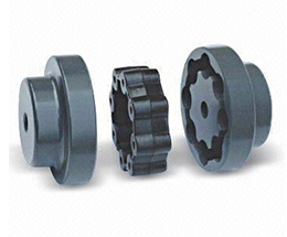
- Jaw Couplings: Jaw couplings feature elastomer spiders that fit between two hubs. They can accommodate angular and parallel misalignment while dampening vibrations.
- Disc Couplings: Disc couplings use thin metallic discs to connect the shafts. They are highly flexible and provide excellent misalignment compensation.
- Gear Couplings: Gear couplings use gear teeth to transmit torque. They offer high torque capacity and can handle moderate misalignment.
- Beam Couplings: Beam couplings use a single piece of flexible material, such as a metal beam, to transmit torque while compensating for misalignment.
- Bellows Couplings: Bellows couplings use a bellows-like structure to allow for axial, angular, and parallel misalignment compensation.
- Oldham Couplings: Oldham couplings use three discs, with the middle one having a perpendicular slot to allow for misalignment compensation.
How a Flexible Coupling Works:
The operation of a flexible coupling depends on its specific design, but the general principles are similar. Let’s take the example of a jaw coupling to explain how a flexible coupling works:
- Two shafts are connected to the coupling hubs on either side, with an elastomer spider placed between them.
- When torque is applied to one shaft, it causes the spider to compress and deform slightly, transmitting the torque to the other shaft.
- In case of misalignment between the shafts, the elastomer spider flexes and compensates for the misalignment, ensuring smooth torque transmission without imposing excessive loads on the shafts or connected equipment.
- The elastomer spider also acts as a damping element, absorbing vibrations and shocks during operation, which reduces wear on the equipment and enhances system stability.
Overall, the flexibility and ability to compensate for misalignment are the key features that allow a flexible coupling to function effectively. The choice of a specific flexible coupling type depends on the application’s requirements, such as torque capacity, misalignment compensation, and environmental conditions.
editor by CX 2024-04-15
China Aluminum alloy bellows coupling shaft high torque motor bellows servo motor spring coupler coupling cast
Warranty: 3 years
Relevant Industries: Hotels, Garment Shops, Developing Material Outlets, Producing Plant, Equipment Restore Shops, Foodstuff & Beverage Manufacturing facility, Farms, Cafe, Property Use, Retail, Printing Outlets, Construction works , Power & Mining, Other, Advertising and marketing Firm, Machine tool gear, Device restore shop
Tailored assist: OEM, New vehicle components for suzuki synchronizer ring24431-74030 24431-74034 24432- 7300 24432-80D00 24431-82042 24432- 60B20 24431 ODM, OBM
Construction: Metallic Bellows
Flexible or Rigid: Versatile
Normal or Nonstandard: Nonstandard
Content: Aluminium
Certification: GS
Packaging Information: Cartons are packed in wooden case
Port: HangZhou Hong Kong in HangZhou
| Description | Bellows Coupling |
| Bushings | 7075 Aluminum Alloy |
| Corrugated Pipe | 301 Stainless steel |
| Clamping Screw | 12.9 Degree |
| Size of Coupling | Stardand, Unstardand Dimension Tailored Offered |
| Types | Clamping + Leading Wire |
| Keyway | Stardand, Unstardand Dimension Custom-made Obtainable |
| Size of Internal Hole | High Precision H7 common |
| Surface Therapy | Oxidation and Not Oxidized (If there is no be aware, it will be transported randomly.) |

Functions and Modifications of Couplings
A coupling is a mechanical device that connects two shafts and transmits power. Its main purpose is to join two rotating pieces of equipment together, and it can also be used to allow some end movement or misalignment. There are many different types of couplings, each serving a specific purpose.
Functions
Functions of coupling are useful tools to study the dynamical interaction of systems. These functions have a wide range of applications, ranging from electrochemical processes to climate processes. The research being conducted on these functions is highly interdisciplinary, and experts from different fields are contributing to this issue. As such, this issue will be of interest to scientists and engineers in many fields, including electrical engineering, physics, and mathematics.
To ensure the proper coupling of data, coupling software must perform many essential functions. These include time interpolation and timing, and data exchange between the appropriate nodes. It should also guarantee that the time step of each model is divisible by the data exchange interval. This will ensure that the data exchange occurs at the proper times.
In addition to transferring power, couplings are also used in machinery. In general, couplings are used to join two rotating pieces. However, they can also have other functions, including compensating for misalignment, dampening axial motion, and absorbing shock. These functions determine the coupling type required.
The coupling strength can also be varied. For example, the strength of the coupling can change from negative to positive. This can affect the mode splitting width. Additionally, coupling strength is affected by fabrication imperfections. The strength of coupling can be controlled with laser non-thermal oxidation and water micro-infiltration, but these methods have limitations and are not reversible. Thus, the precise control of coupling strength remains a major challenge.
Applications
Couplings transmit power from a driver to the driven piece of equipment. The driver can be an electric motor, steam turbine, gearbox, fan, or pump. A coupling is often the weak link in a pump assembly, but replacing it is less expensive than replacing a sheared shaft.
Coupling functions have wide applications, including biomedical and electrical engineering. In this book, we review some of the most important developments and applications of coupling functions in these fields. We also discuss the future of the field and the implications of these discoveries. This is a comprehensive review of recent advances in coupling functions, and will help guide future research.
Adaptable couplings are another type of coupling. They are made up of a male and female spline in a polymeric material. They can be mounted using traditional keys, keyways, or taper bushings. For applications that require reversal, however, keyless couplings are preferable. Consider your process speed, maximum load capacity, and torque when choosing an adaptable coupling.
Coupling reactions are also used to make pharmaceutical products. These chemical reactions usually involve the joining of two chemical species. In most cases, a metal catalyst is used. The Ullmann reaction, for instance, is an important example of a hetero-coupling reaction. This reaction involves an organic halide with an organometallic compound. The result is a compound with the general formula R-M-R. Another important coupling reaction involves the Suzuki coupling, which unites two chemical species.
In engineering, couplings are mechanical devices that connect two shafts. Couplings are important because they enable the power to be transmitted from one end to the other without allowing a shaft to separate during operation. They also reduce maintenance time. Proper selection, installation, and maintenance, will reduce the amount of time needed to repair a coupling.
Maintenance
Maintenance of couplings is an important part of the lifecycle of your equipment. It’s important to ensure proper alignment and lubrication to keep them running smoothly. Inspecting your equipment for signs of wear can help you identify problems before they cause downtime. For instance, improper alignment can lead to uneven wear of the coupling’s hubs and grids. It can also cause the coupling to bind when you rotate the shaft manually. Proper maintenance will extend the life of your coupling.
Couplings should be inspected frequently and thoroughly. Inspections should go beyond alignment checks to identify problems and recommend appropriate repairs or replacements. Proper lubrication is important to protect the coupling from damage and can be easily identified using thermography or vibration analysis. In addition to lubrication, a coupling that lacks lubrication may require gaskets or sealing rings.
Proper maintenance of couplings will extend the life of the coupling by minimizing the likelihood of breakdowns. Proper maintenance will help you save money and time on repairs. A well-maintained coupling can be a valuable asset for your equipment and can increase productivity. By following the recommendations provided by your manufacturer, you can make sure your equipment is operating at peak performance.
Proper alignment and maintenance are critical for flexible couplings. Proper coupling alignment will maximize the life of your equipment. If you have a poorly aligned coupling, it may cause other components to fail. In some cases, this could result in costly downtime and increased costs for the company.
Proper maintenance of couplings should be done regularly to minimize costs and prevent downtime. Performing periodic inspections and lubrication will help you keep your equipment in top working order. In addition to the alignment and lubrication, you should also inspect the inside components for wear and alignment issues. If your coupling’s lubrication is not sufficient, it may lead to hardening and cracking. In addition, it’s possible to develop leaks that could cause damage.
Modifications
The aim of this paper is to investigate the effects of coupling modifications. It shows that such modifications can adversely affect the performance of the coupling mechanism. Moreover, the modifications can be predicted using chemical physics methods. The results presented here are not exhaustive and further research is needed to understand the effects of such coupling modifications.
The modifications to coupling involve nonlinear structural modifications. Four examples of such modifications are presented. Each is illustrated with example applications. Then, the results are verified through experimental and simulated case studies. The proposed methods are applicable to large and complex structures. They are applicable to a variety of engineering systems, including nonlinear systems.
editor by CX 2023-07-04
China High Torque Disk Type Coupling Shaft Coupling Servo Motor Coupling coupling contractions
Product Description
| Product No. | φD | L | W | L1 | M | Tighten the toughness(N.m) |
| SG7-8-C19- | 19.5 | twenty | 1.2 | nine.4 | M2.5 | one |
| SG7-8-C26- | 26 | twenty five.5 | two.5 | eleven.5 | M3 | one.5 |
| SG7-8-C34- | 34 | 32.three | 3.three | fourteen.5 | M4 | one.five |
| SG7-8-C39- | 39 | 34.one | four.one | 15 | M4 | two.five |
| SG7-8-C44- | 44 | 34.five | 4.5 | 15 | M4 | 2.5 |
| SG7-8-C50- | fifty | 40.five | 4.five | 18 | M5 | seven |
| SG7-8-C56- | fifty six | forty five | five | 20 | M5 | seven |
| SG7-8-C68- | sixty eight | 54 | 6 | 24 | M6 | 12 |
| SG7-8-C82- | eighty two | sixty eight | 8 | 30 | M8 | sixteen |
| SG7-8-C94- | 94 | 68 | eight | thirty | M8 | 28 |
| SG7-8-C104- | 104 | 70 | 10 | 30 | M8 | 28 |
| Product No. | Rated torque | Maximum Torque | Max Speed | Inertia Minute | N.m rad | RRO | Tilting Tolerance | End-play | Fat:(g) |
| SG7-8-C19- | 1N.m | 2N.m | 10000prm | .65×10-6kg.m² | 200N.m/rad | .04mm | 1c | ±0.2mm | 12 |
| SG7-8-C26- | 1.4N.m | 2.8N.m | 10000prm | one.8×10-6kg.m² | 690N.m/rad | .04mm | 1c | ±0.2mm | 31 |
| SG7-8-C34- | 2.8N.m | 5.6N.m | 10000prm | 7.2×10⁻⁶kg.m² | 1650N.m/rad | .04mm | 1c | ±0.2mm | 64 |
| SG7-8-C39- | 5.8N.m | 11.6N.m | 10000prm | one.8×10-5kg.m² | 2500N.m/rad | .04mm | 1c | ±0.2mm | ninety seven |
| SG7-8-C44- | eight.7N.m | seventeen.4N.m | 10000prm | two.5×10-5kg.m² | 2900N.m/rad | .04mm | 1c | ±0.2mm | 113 |
| SG7-8-C50- | 15N.m | 30N.m | 10000prm | 8.2×10⁻⁵kg.m² | 6700N.m/rad | .04mm | 1c | ±0.2mm | 195 |
| SG7-8-C56- | 25N.m | 50N.m | 10000prm | 1×10⁻⁴kg.m² | 8400N.m/rad | .04mm | 1c | ±0.2mm | 263 |
| SG7-8-C68- | 55N.m | 110N.m | 10000prm | one.9×10-4kg.m² | 11500N.m/rad | .04mm | 1c | ±0.2mm | 445 |
| SG7-8-C82- | 80N.m | 160N.m | 10000prm | 7×10⁻⁴kg.m² | 14550N.m/rad | .04mm | 1c | ±0.2mm | 892 |
| SG7-8-C94- | 185N.m | 370N.m | 10000prm | 1.23×10⁻³kg.m² | 16900N.m/rad | .04mm | 1c | ±0.2mm | 950 |
| SG7-8-C104- | 255N.m | 510N.m | 10000prm | 1.86×10⁻³kg.m² | 25100N.m/rad | .04mm | 1c | ±0.2mm | 1190 |
|
US $12-32 / Piece | |
1 Piece (Min. Order) |
###
| Standard Or Nonstandard: | Nonstandard |
|---|---|
| Shaft Hole: | Customized |
| Torque: | 2-250n.M |
| Bore Diameter: | Customized |
| Speed: | 10000r/M |
| Structure: | Flexible |
###
| Item No. | φD | L | W | L1 | M | Tighten the strength(N.m) |
| SG7-8-C19- | 19.5 | 20 | 1.2 | 9.4 | M2.5 | 1 |
| SG7-8-C26- | 26 | 25.5 | 2.5 | 11.5 | M3 | 1.5 |
| SG7-8-C34- | 34 | 32.3 | 3.3 | 14.5 | M4 | 1.5 |
| SG7-8-C39- | 39 | 34.1 | 4.1 | 15 | M4 | 2.5 |
| SG7-8-C44- | 44 | 34.5 | 4.5 | 15 | M4 | 2.5 |
| SG7-8-C50- | 50 | 40.5 | 4.5 | 18 | M5 | 7 |
| SG7-8-C56- | 56 | 45 | 5 | 20 | M5 | 7 |
| SG7-8-C68- | 68 | 54 | 6 | 24 | M6 | 12 |
| SG7-8-C82- | 82 | 68 | 8 | 30 | M8 | 16 |
| SG7-8-C94- | 94 | 68 | 8 | 30 | M8 | 28 |
| SG7-8-C104- | 104 | 70 | 10 | 30 | M8 | 28 |
###
| Item No. | Rated torque | Maximum Torque | Max Speed | Inertia Moment | N.m rad | RRO | Tilting Tolerance | End-play | Weight:(g) |
| SG7-8-C19- | 1N.m | 2N.m | 10000prm | 0.65×10⁻⁶kg.m² | 200N.m/rad | 0.04mm | 1c | ±0.2mm | 12 |
| SG7-8-C26- | 1.4N.m | 2.8N.m | 10000prm | 1.8×10⁻⁶kg.m² | 690N.m/rad | 0.04mm | 1c | ±0.2mm | 31 |
| SG7-8-C34- | 2.8N.m | 5.6N.m | 10000prm | 7.2×10⁻⁶kg.m² | 1650N.m/rad | 0.04mm | 1c | ±0.2mm | 64 |
| SG7-8-C39- | 5.8N.m | 11.6N.m | 10000prm | 1.8×10⁻⁵kg.m² | 2500N.m/rad | 0.04mm | 1c | ±0.2mm | 97 |
| SG7-8-C44- | 8.7N.m | 17.4N.m | 10000prm | 2.5×10⁻⁵kg.m² | 2900N.m/rad | 0.04mm | 1c | ±0.2mm | 113 |
| SG7-8-C50- | 15N.m | 30N.m | 10000prm | 8.2×10⁻⁵kg.m² | 6700N.m/rad | 0.04mm | 1c | ±0.2mm | 195 |
| SG7-8-C56- | 25N.m | 50N.m | 10000prm | 1×10⁻⁴kg.m² | 8400N.m/rad | 0.04mm | 1c | ±0.2mm | 263 |
| SG7-8-C68- | 55N.m | 110N.m | 10000prm | 1.9×10⁻⁴kg.m² | 11500N.m/rad | 0.04mm | 1c | ±0.2mm | 445 |
| SG7-8-C82- | 80N.m | 160N.m | 10000prm | 7×10⁻⁴kg.m² | 14550N.m/rad | 0.04mm | 1c | ±0.2mm | 892 |
| SG7-8-C94- | 185N.m | 370N.m | 10000prm | 1.23×10⁻³kg.m² | 16900N.m/rad | 0.04mm | 1c | ±0.2mm | 950 |
| SG7-8-C104- | 255N.m | 510N.m | 10000prm | 1.86×10⁻³kg.m² | 25100N.m/rad | 0.04mm | 1c | ±0.2mm | 1190 |
Types of Couplings
A coupling is a device used to join two shafts together and transmit power. Its purpose is to join rotating equipment while permitting a degree of end movement and misalignment. There are many types of couplings, and it is important to choose the right one for your application. Here are a few examples of couplings.
Mechanical
The mechanical coupling is an important component in power transmission systems. These couplings come in various forms and can be used in different types of applications. They can be flexible or rigid and operate in compression or shear. In some cases, they are permanently attached to the shaft, while in other cases, they are removable for service.
The simplest type of mechanical coupling is the sleeve coupling. It consists of a cylindrical sleeve with an internal diameter equal to the diameter of the shafts. The sleeve is connected to the shafts by a key that restricts their relative motion and prevents slippage. A few sleeve couplings also have threaded holes to prevent axial movement. This type of coupling is typically used for medium to light-duty torque.
Another type of mechanical coupling is a jaw coupling. It is used in motion control and general low-power transmission applications. This type of coupling does not require lubrication and is capable of accommodating angular misalignment. Unlike other types of couplings, the jaw coupling uses two hubs with intermeshing jaws. The jaw coupling’s spider is typically made of copper alloys. In addition, it is suitable for shock and vibration loads.
Mechanical couplings can be made from a variety of materials. One popular choice is rubber. The material can be natural or chloroprene. These materials are flexible and can tolerate slight misalignment.
Electrical
Electrical coupling is the process in which a single electrical signal is transferred from a nerve cell to another. It occurs when electrical signals from two nerve cells interact with each other in a way similar to haptic transmission. This type of coupling can occur on its own or in combination with electrotonic coupling in gap junctions.
Electrical coupling is often associated with oscillatory behavior of neurons. The mechanism of electrical coupling is complex and is studied mathematically to understand its effect on oscillatory neuron networks. For example, electrical coupling can increase or decrease the frequency of an oscillator, depending on the state of the neuron coupled to it.
The site of coupling is usually the junction of opposing cell membranes. The cellular resistance and the coupling resistance are measured in voltage-clamp experiments. This type of coupling has a specific resistance of 100 O-cm. As a result, the coupling resistance varies with the frequency.
The authors of this study noted that electrotonic coupling depends on the ratio between the resistance of the nonjunctional membranes and the junctional membranes. The voltage attenuation technique helps reveal the differences in resistance and shunting through the intercellular medium. However, it is unclear whether electrotonic coupling is electrostatically mediated.
Electrical coupling has also been suggested to play a role in the intercellular transfer of information. There are many examples that support this theory. A message can be a distinct qualitative or quantitative signal, which results in a gradient in the cells. Although gap junctions are absent at many embryonic interaction sites, increasing evidence suggests a role in information transfer.
Flexible
When it comes to choosing the right Flexible Coupling, there are several factors that you should take into account. Among these factors is the backlash that can be caused by the movement of the coupling. The reason for this problem is the fact that couplings that do not have anti-fungal properties can be easily infected by mold. The best way to avoid this is to pay attention to the moisture content of the area where you are installing the coupling. By following these guidelines, you can ensure the best possible installation.
To ensure that you are getting the most out of your flexible couplings, you must consider their characteristics and how easy they are to install, assemble, and maintain. You should also look for elements that are field-replaceable. Another important factor is the coupling’s torsional rigidity. It should also be able to handle reactionary loads caused by misalignment.
Flexible couplings come in many different types. There are diaphragm and spiral couplings. These couplings allow for axial motion, angular misalignment, and parallel offset. They have one-piece construction and are made from stainless steel or aluminum. These couplings also offer high torsional stiffness, which is beneficial for applications requiring high torques.
Flexible couplings have several advantages over their rigid counterparts. They are designed to handle misalignments of up to seven degrees and 0.025 inches. These characteristics are important in motion control applications. Flexible couplings are also inexpensive, and they do not require maintenance.
Beam
A beam coupling is a type of mechanical coupling, usually one solid piece, that connects two mechanical parts. Its performance is largely determined by the material used. Typical materials include stainless steel, aluminum, Delrin, and titanium. The beam coupling is rated for different speeds and torques. The coupling should be selected according to the application. In addition to the material, the application should also consider the speed and torque of the system.
There are two main types of beam couplings. The first is the helical beam coupling, which has a continuous multi spiral cut. This type of coupling offers a high degree of flexibility and compensates for a high degree of misalignment. The second type of beam coupling is the helical shaft coupling, which has a low torsional stiffness, which makes it ideal for small torque applications.
Another type of beam coupling is the multiple beam design, which combines two beams. It allows for more tolerance in manufacturing and installation and protects expensive components from excessive bearing loads. It also helps keep beams shorter than a single beam coupling. This type of coupling also enables a higher torque capacity and torsional stiffness.
Beam couplings can be manufactured with different materials, including stainless steel and aluminum. The “A” series is available in aluminum and stainless steel and is ideal for general-purpose and light-duty applications. It is also economical and durable. This type of coupling can also be used with low torque pumps or encoder/resolver systems.
Pin & bush
The Pin & bush coupling is a versatile, general-purpose coupling with high tensile bolts and rubber bushes. It can tolerate a wide range of operating temperatures and is suitable for use in oil and water-resistance applications. Its unique design enables it to be used in either direction. In addition, it requires no lubrication.
The pin bush coupling is a fail-safe coupling with a long service life and is used for high-torque applications. It provides torsional flexibility and dampens shocks, making it a flexible coupling that protects equipment and reduces maintenance costs. Its hubs are forged from graded cast iron for strength and durability. Besides, the coupling’s elastomer elements reduce vibration and impact loads. It also accommodates a misalignment of up to 0.5 degrees.
Pin & bush couplings are a popular choice for a variety of different applications. This coupling features a protective flange design that protects the coupling flange from wear and tear. The coupling nut is secured to one flange, while a rubber or leather bush sits between the other flange. Its unique design makes it ideal for use in applications where misalignment is a small factor. The rubber bushing also helps absorb vibration and shock.
Mesh tooth
Mesh tooth couplings are used to transfer torque between two shafts and reduce backlash. However, mesh tooth couplings have some limitations. One disadvantage is the break-away friction factor in the axial direction. This problem is caused by the high contact force between the tooth and gear mesh. This can cause unpredictable forces on the shafts.
In this paper, we present a FEM model for mesh tooth coupling. We first validate the mesh density. To do so, we compute the bolt stress as a uniaxial tensile during the tightening process. We used different mesh sizes and mesh density to validate our results.
The mesh stiffness of gear pairs is influenced by lead crown relief and misalignment. For example, if one tooth is positioned too far in the axis, the mesh stiffness will be decreased. A misaligned gear pair will lose torque capacity. A mesh tooth coupling can be lubricated with oil.
An ideal mesh tooth coupling has no gaps between the teeth, which reduces the risk of uneven wear. The coupling’s quality exposed fasteners include SAE Grade 5 bolts. It also offers corrosion resistance. The couplings are compatible with industrial environments. They also eliminate the need for selective assembly in sleeve couplings.
editor by czh 2023-01-31
China Servo Coupling
Rotating shaft-driven mechanical components are commonly used in all forms of machinery that perform the various processes and functions of modern industry.
- Shaft misalignment will place stresses on shafts and related parts of the assembly such as bearings, which can result in early failure of both.
- Shaft ends can be misaligned radially or angularly, exhibit axial displacement, or experience a combination of all 3.
- Drive couplings can be used to compensate for shaft misalignment, whether the misalignment is an intentional or an unintentional part of the design.
Stiffness and Torsional Vibration of Spline-Couplings
In this paper, we describe some basic characteristics of spline-coupling and examine its torsional vibration behavior. We also explore the effect of spline misalignment on rotor-spline coupling. These results will assist in the design of improved spline-coupling systems for various applications. The results are presented in Table 1.
Stiffness of spline-coupling
The stiffness of a spline-coupling is a function of the meshing force between the splines in a rotor-spline coupling system and the static vibration displacement. The meshing force depends on the coupling parameters such as the transmitting torque and the spline thickness. It increases nonlinearly with the spline thickness.
A simplified spline-coupling model can be used to evaluate the load distribution of splines under vibration and transient loads. The axle spline sleeve is displaced a z-direction and a resistance moment T is applied to the outer face of the sleeve. This simple model can satisfy a wide range of engineering requirements but may suffer from complex loading conditions. Its asymmetric clearance may affect its engagement behavior and stress distribution patterns.
The results of the simulations show that the maximum vibration acceleration in both Figures 10 and 22 was 3.03 g/s. This results indicate that a misalignment in the circumferential direction increases the instantaneous impact. Asymmetry in the coupling geometry is also found in the meshing. The right-side spline’s teeth mesh tightly while those on the left side are misaligned.
Considering the spline-coupling geometry, a semi-analytical model is used to compute stiffness. This model is a simplified form of a classical spline-coupling model, with submatrices defining the shape and stiffness of the joint. As the design clearance is a known value, the stiffness of a spline-coupling system can be analyzed using the same formula.
The results of the simulations also show that the spline-coupling system can be modeled using MASTA, a high-level commercial CAE tool for transmission analysis. In this case, the spline segments were modeled as a series of spline segments with variable stiffness, which was calculated based on the initial gap between spline teeth. Then, the spline segments were modelled as a series of splines of increasing stiffness, accounting for different manufacturing variations. The resulting analysis of the spline-coupling geometry is compared to those of the finite-element approach.
Despite the high stiffness of a spline-coupling system, the contact status of the contact surfaces often changes. In addition, spline coupling affects the lateral vibration and deformation of the rotor. However, stiffness nonlinearity is not well studied in splined rotors because of the lack of a fully analytical model.
Characteristics of spline-coupling
The study of spline-coupling involves a number of design factors. These include weight, materials, and performance requirements. Weight is particularly important in the aeronautics field. Weight is often an issue for design engineers because materials have varying dimensional stability, weight, and durability. Additionally, space constraints and other configuration restrictions may require the use of spline-couplings in certain applications.
The main parameters to consider for any spline-coupling design are the maximum principal stress, the maldistribution factor, and the maximum tooth-bearing stress. The magnitude of each of these parameters must be smaller than or equal to the external spline diameter, in order to provide stability. The outer diameter of the spline must be at least 4 inches larger than the inner diameter of the spline.
Once the physical design is validated, the spline coupling knowledge base is created. This model is pre-programmed and stores the design parameter signals, including performance and manufacturing constraints. It then compares the parameter values to the design rule signals, and constructs a geometric representation of the spline coupling. A visual model is created from the input signals, and can be manipulated by changing different parameters and specifications.
The stiffness of a spline joint is another important parameter for determining the spline-coupling stiffness. The stiffness distribution of the spline joint affects the rotor’s lateral vibration and deformation. A finite element method is a useful technique for obtaining lateral stiffness of spline joints. This method involves many mesh refinements and requires a high computational cost.
The diameter of the spline-coupling must be large enough to transmit the torque. A spline with a larger diameter may have greater torque-transmitting capacity because it has a smaller circumference. However, the larger diameter of a spline is thinner than the shaft, and the latter may be more suitable if the torque is spread over a greater number of teeth.
Spline-couplings are classified according to their tooth profile along the axial and radial directions. The radial and axial tooth profiles affect the component’s behavior and wear damage. Splines with a crowned tooth profile are prone to angular misalignment. Typically, these spline-couplings are oversized to ensure durability and safety.
Stiffness of spline-coupling in torsional vibration analysis
This article presents a general framework for the study of torsional vibration caused by the stiffness of spline-couplings in aero-engines. It is based on a previous study on spline-couplings. It is characterized by the following 3 factors: bending stiffness, total flexibility, and tangential stiffness. The first criterion is the equivalent diameter of external and internal splines. Both the spline-coupling stiffness and the displacement of splines are evaluated by using the derivative of the total flexibility.
The stiffness of a spline joint can vary based on the distribution of load along the spline. Variables affecting the stiffness of spline joints include the torque level, tooth indexing errors, and misalignment. To explore the effects of these variables, an analytical formula is developed. The method is applicable for various kinds of spline joints, such as splines with multiple components.
Despite the difficulty of calculating spline-coupling stiffness, it is possible to model the contact between the teeth of the shaft and the hub using an analytical approach. This approach helps in determining key magnitudes of coupling operation such as contact peak pressures, reaction moments, and angular momentum. This approach allows for accurate results for spline-couplings and is suitable for both torsional vibration and structural vibration analysis.
The stiffness of spline-coupling is commonly assumed to be rigid in dynamic models. However, various dynamic phenomena associated with spline joints must be captured in high-fidelity drivetrain models. To accomplish this, a general analytical stiffness formulation is proposed based on a semi-analytical spline load distribution model. The resulting stiffness matrix contains radial and tilting stiffness values as well as torsional stiffness. The analysis is further simplified with the blockwise inversion method.
It is essential to consider the torsional vibration of a power transmission system before selecting the coupling. An accurate analysis of torsional vibration is crucial for coupling safety. This article also discusses case studies of spline shaft wear and torsionally-induced failures. The discussion will conclude with the development of a robust and efficient method to simulate these problems in real-life scenarios.
Effect of spline misalignment on rotor-spline coupling
In this study, the effect of spline misalignment in rotor-spline coupling is investigated. The stability boundary and mechanism of rotor instability are analyzed. We find that the meshing force of a misaligned spline coupling increases nonlinearly with spline thickness. The results demonstrate that the misalignment is responsible for the instability of the rotor-spline coupling system.
An intentional spline misalignment is introduced to achieve an interference fit and 0 backlash condition. This leads to uneven load distribution among the spline teeth. A further spline misalignment of 50um can result in rotor-spline coupling failure. The maximum 10sile root stress shifted to the left under this condition.
Positive spline misalignment increases the gear mesh misalignment. Conversely, negative spline misalignment has no effect. The right-handed spline misalignment is opposite to the helix hand. The high contact area is moved from the center to the left side. In both cases, gear mesh is misaligned due to deflection and tilting of the gear under load.
This variation of the tooth surface is measured as the change in clearance in the transverse plain. The radial and axial clearance values are the same, while the difference between the 2 is less. In addition to the frictional force, the axial clearance of the splines is the same, which increases the gear mesh misalignment. Hence, the same procedure can be used to determine the frictional force of a rotor-spline coupling.
Gear mesh misalignment influences spline-rotor coupling performance. This misalignment changes the distribution of the gear mesh and alters contact and bending stresses. Therefore, it is essential to understand the effects of misalignment in spline couplings. Using a simplified system of helical gear pair, Hong et al. examined the load distribution along the tooth interface of the spline. This misalignment caused the flank contact pattern to change. The misaligned teeth exhibited deflection under load and developed a tilting moment on the gear.
The effect of spline misalignment in rotor-spline couplings is minimized by using a mechanism that reduces backlash. The mechanism comprises cooperably splined male and female members. One member is formed by 2 coaxially aligned splined segments with end surfaces shaped to engage in sliding relationship. The connecting device applies axial loads to these segments, causing them to rotate relative to 1 another.

