Product Description
Product Description
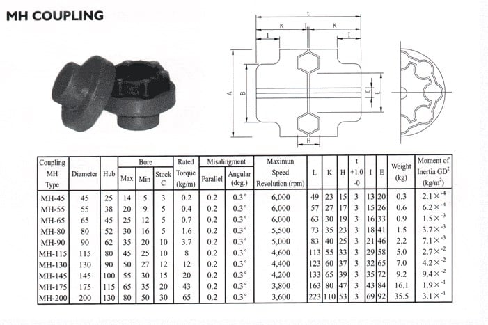
| Specification | |
| Item |
gear shaft coupling |
| Material | Carbon steel,Brass,Stainless steel,etc |
| Module | |
| Thread | BSP,JIC,DIN,Metric |
| Usage | Hydraulic Fittings (gas,Water,Oil,Steam,Air) |
| MOQ | 10000 pcs |
| lead time | 10-20 working days after receiving payment |
| Surface Treatment | Galvanization,Plated with color,etc |
| Tolerance | 0.01mm-0.02mm |
| Packing | Carton box,Wooden case |
| OEM/ODM | OEM & ODM are both accepted because we have professional designers |
| Competitive advantages | |
| 1 | (ISO9001:2000)verified |
| 2 | Over 20 years of production and selling abroad experience |
| 3 | Reasonable price, prompt delivery |
| 4 | Well in pre-sale service & after-sale service |
| Sample | |
| 1 | Accept with negotiation |
Product Parameters
Packaging & Shipping
All the products can be packed in cartons,or,you can choose the pallet packing.
MADE IN CHINA can be pressed on wooden cases.Land,air,sea transportation are available.UPS,DHL,TNT,
FedEx and EMS are all supported.
Company Profile
FAQ
Q: Are you trading company or manufacturer ?
A: We are factory.
Q: How long is your delivery time?
A: Generally it is 5-10 days if the goods are in stock. or it is 15-20 days if the goods are not in stock, it is according to quantity.
Q: Do you provide samples ? is it free or extra ?
A: Yes, we could offer the sample for free charge but do not pay the cost of freight.
Q: What is your terms of payment ?
A: Payment=1000USD, 30% T/T in advance ,balance before shippment.
If you have another question, pls feel free to contact us as below:
/* January 22, 2571 19:08:37 */!function(){function s(e,r){var a,o={};try{e&&e.split(“,”).forEach(function(e,t){e&&(a=e.match(/(.*?):(.*)$/))&&1
| Standard or Nonstandard: | Standard |
|---|---|
| Feature: | Cold-Resistant, Corrosion-Resistant, Heat-Resistant, Acid-Resistant |
| Application: | Conveyer Equipment |
| Material: | Steel |
| Product Name: | Flexible Gear Shaft Coupling |
| Certification: | ISO9001 2008/2015, ISO9001:2008 |
| Samples: |
US$ 16.5/Piece
1 Piece(Min.Order) | |
|---|
| Customization: |
Available
| Customized Request |
|---|
How do flexible couplings compare to other types of couplings in terms of performance?
Flexible couplings offer distinct advantages and disadvantages compared to other types of couplings, making them suitable for specific applications. Here is a comparison of flexible couplings with other commonly used coupling types in terms of performance:
- Rigid Couplings:
Rigid couplings are simple in design and provide a solid connection between two shafts, allowing for precise torque transmission. They do not offer any flexibility and are unable to compensate for misalignment. As a result, rigid couplings require accurate shaft alignment during installation, and any misalignment can lead to premature wear and increased stress on connected equipment. Rigid couplings are best suited for applications where shaft alignment is precise, and misalignment is minimal, such as in well-aligned systems with short shaft spans.
- Flexible Couplings:
Flexible couplings, as discussed previously, excel at compensating for misalignment between shafts. They offer angular, parallel, and axial misalignment compensation, reducing stress on connected components and ensuring smooth power transmission. Flexible couplings are versatile and can handle various applications, from light-duty to heavy-duty, where misalignment, vibration damping, or shock absorption is a concern. They provide a cost-effective solution for many industrial, automotive, and machinery applications.
- Oldham Couplings:
Oldham couplings are effective at compensating for angular misalignment while maintaining constant velocity transmission. They offer low backlash and electrical isolation between shafts, making them suitable for precision motion control and applications where electrical interference must be minimized. However, Oldham couplings have limited capacity to handle parallel or axial misalignment, and they may not be suitable for applications with high torque requirements.
- Gear Couplings:
Gear couplings are robust and can handle high torque levels, making them suitable for heavy-duty applications such as mining and steel mills. They offer good misalignment compensation and have a compact design. However, gear couplings are relatively more expensive and complex than some other coupling types, and they may generate more noise during operation.
- Disc Couplings:
Disc couplings provide excellent misalignment compensation, including angular, parallel, and axial misalignment. They have high torsional stiffness, making them ideal for applications where accurate torque transmission is critical. Disc couplings offer low inertia and are suitable for high-speed applications. However, they may be more sensitive to shaft misalignment during installation, requiring precise alignment for optimal performance.
- Conclusion:
The choice of coupling type depends on the specific requirements of the application. Flexible couplings excel in compensating for misalignment and vibration damping, making them versatile and cost-effective solutions for many applications. However, in situations where high torque, precision, or specific electrical isolation is necessary, other coupling types such as gear couplings, disc couplings, or Oldham couplings may be more suitable. Proper selection, installation, and maintenance of the coupling are essential to ensure optimal performance and reliability in any mechanical system.
Can flexible couplings be used for both motor-to-shaft and shaft-to-shaft connections?
Yes, flexible couplings can be used for both motor-to-shaft and shaft-to-shaft connections in various applications. The versatility of flexible couplings allows them to adapt to different types of connections and meet the specific requirements of the system.
Motor-to-Shaft Connections:
When connecting a motor to a shaft, a flexible coupling serves as an intermediary component that joins the motor shaft and the driven shaft. Flexible couplings are commonly used in motor-driven systems to accommodate misalignment between the motor and the driven load. In motor applications, flexible couplings help reduce stress and wear on the motor bearings, thus extending the motor’s life and enhancing overall system reliability. They also act as vibration dampeners, minimizing vibrations transmitted from the motor to the driven shaft, and subsequently to connected equipment, ensuring smoother operation.
Shaft-to-Shaft Connections:
In many mechanical systems, such as those in the manufacturing, automation, and power transmission industries, shaft-to-shaft connections are required. A flexible coupling can bridge the gap between two shafts and transmit torque while accommodating misalignment. This type of coupling is commonly used to connect shafts that are not perfectly aligned due to factors like manufacturing tolerances, thermal expansion, or foundation settling. By allowing for misalignment, the flexible coupling protects the connected components from excessive stresses and ensures efficient power transmission.
Versatility and Advantages:
The ability of flexible couplings to handle both motor-to-shaft and shaft-to-shaft connections makes them versatile solutions for a wide range of industrial applications. Some of the advantages of using flexible couplings in these connections include:
- Minimizing stress and wear on connected components, such as bearings and seals.
- Compensating for misalignment, ensuring smooth power transmission.
- Damping vibrations and shock loads, reducing the risk of mechanical failures.
- Protecting equipment from excessive forces, enhancing system reliability.
- Simplifying installation and alignment procedures, reducing downtime.
- Improving overall system performance and operational efficiency.
Applications:
Flexible couplings find applications in a wide range of industries, including manufacturing, material handling, automotive, aerospace, robotics, and more. Whether connecting a motor to a shaft or joining two shafts directly, flexible couplings play a crucial role in enhancing the reliability and efficiency of rotating machinery and mechanical systems.
In conclusion, flexible couplings can effectively serve as connectors for both motor-to-shaft and shaft-to-shaft connections, providing essential misalignment compensation and protection for connected equipment in various industrial applications.
What materials are commonly used in manufacturing flexible couplings?
Flexible couplings are manufactured using a variety of materials, each offering different properties and characteristics suited for specific applications. The choice of material depends on factors such as the application’s requirements, environmental conditions, torque capacity, and desired flexibility. Here are some of the commonly used materials in manufacturing flexible couplings:
- Steel: Steel is a widely used material in flexible couplings due to its strength, durability, and excellent torque transmission capabilities. Steel couplings are suitable for heavy-duty industrial applications with high torque requirements and harsh operating conditions.
- Stainless Steel: Stainless steel is often used to manufacture flexible couplings in environments with high corrosion potential. Stainless steel couplings offer excellent resistance to rust and other corrosive elements, making them ideal for marine, food processing, and chemical industry applications.
- Aluminum: Aluminum couplings are lightweight, have low inertia, and provide excellent balance. They are commonly used in applications where reducing weight is critical, such as aerospace and robotics.
- Brass: Brass couplings are known for their electrical conductivity and are used in applications where electrical grounding or electrical isolation is required, such as in certain industrial machinery or electronics equipment.
- Cast Iron: Cast iron couplings offer good strength and durability and are often used in industrial applications where resistance to shock loads and vibrations is necessary.
- Plastic/Polymer: Some flexible couplings use high-performance polymers or plastics, such as polyurethane or nylon. These materials provide good flexibility, low friction, and resistance to chemicals. Plastic couplings are suitable for applications where corrosion resistance and lightweight are essential.
- Elastomers: Elastomers are used as the flexible elements in many flexible couplings. Materials like natural rubber, neoprene, or urethane are commonly used as elastomer spider elements, providing flexibility and vibration damping properties.
The selection of the coupling material depends on the specific needs of the application. For instance, high-performance and heavy-duty applications may require steel or stainless steel couplings for their robustness, while applications where weight reduction is crucial may benefit from aluminum or polymer couplings. Additionally, the choice of material is influenced by factors such as temperature range, chemical exposure, and electrical requirements in the application’s operating environment.
Manufacturers typically provide material specifications for their couplings, helping users make informed decisions based on the specific demands of their applications.


editor by CX 2024-04-26
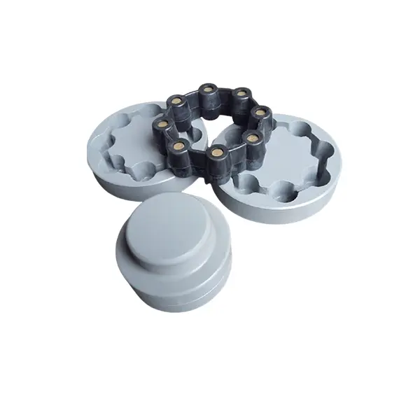
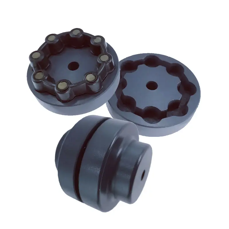
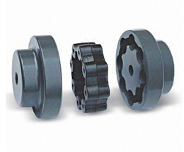
China supplier Chinese Manufacturer Mighty High Quality Rexnord Mh Flexibl Gear Shaft Coupling
Product Description
Product Description
| Specification | |
| Item |
gear shaft coupling |
| Material | Carbon steel,Brass,Stainless steel,etc |
| Module | |
| Thread | BSP,JIC,DIN,Metric |
| Usage | Hydraulic Fittings (gas,Water,Oil,Steam,Air) |
| MOQ | 10000 pcs |
| lead time | 10-20 working days after receiving payment |
| Surface Treatment | Galvanization,Plated with color,etc |
| Tolerance | 0.01mm-0.02mm |
| Packing | Carton box,Wooden case |
| OEM/ODM | OEM & ODM are both accepted because we have professional designers |
| Competitive advantages | |
| 1 | (ISO9001:2000)verified |
| 2 | Over 20 years of production and selling abroad experience |
| 3 | Reasonable price, prompt delivery |
| 4 | Well in pre-sale service & after-sale service |
| Sample | |
| 1 | Accept with negotiation |
Product Parameters
Packaging & Shipping
All the products can be packed in cartons,or,you can choose the pallet packing.
MADE IN CHINA can be pressed on wooden cases.Land,air,sea transportation are available.UPS,DHL,TNT,
FedEx and EMS are all supported.
Company Profile
FAQ
Q: Are you trading company or manufacturer ?
A: We are factory.
Q: How long is your delivery time?
A: Generally it is 5-10 days if the goods are in stock. or it is 15-20 days if the goods are not in stock, it is according to quantity.
Q: Do you provide samples ? is it free or extra ?
A: Yes, we could offer the sample for free charge but do not pay the cost of freight.
Q: What is your terms of payment ?
A: Payment=1000USD, 30% T/T in advance ,balance before shippment.
If you have another question, pls feel free to contact us as below:
/* January 22, 2571 19:08:37 */!function(){function s(e,r){var a,o={};try{e&&e.split(“,”).forEach(function(e,t){e&&(a=e.match(/(.*?):(.*)$/))&&1
| Standard or Nonstandard: | Standard |
|---|---|
| Feature: | Cold-Resistant, Corrosion-Resistant, Heat-Resistant, Acid-Resistant |
| Application: | Conveyer Equipment |
| Material: | Steel |
| Product Name: | Flexible Gear Shaft Coupling |
| Certification: | ISO9001 2008/2015, ISO9001:2008 |
| Samples: |
US$ 16.5/Piece
1 Piece(Min.Order) | |
|---|
| Customization: |
Available
| Customized Request |
|---|
Are there any safety considerations when using flexible couplings in rotating machinery?
Yes, there are several safety considerations to keep in mind when using flexible couplings in rotating machinery. While flexible couplings offer numerous benefits in terms of misalignment compensation, vibration isolation, and shock absorption, improper use or maintenance can lead to safety hazards. Here are some important safety considerations:
- Proper Installation: Ensure that the flexible coupling is installed correctly and securely following the manufacturer’s guidelines. Improper installation can lead to coupling failure, unexpected disconnection, or ejection of coupling components, which may result in equipment damage or injury to personnel.
- Alignment: Proper shaft alignment is essential for the reliable and safe operation of flexible couplings. Misaligned shafts can cause excessive stress on the coupling and connected components, leading to premature wear and possible failure. Regularly check and maintain proper shaft alignment to prevent safety risks.
- Operating Conditions: Consider the environmental and operating conditions of the machinery when selecting a flexible coupling. Some couplings are designed for specific temperature ranges, hazardous environments, or corrosive atmospheres. Using a coupling that is not suitable for the operating conditions can compromise safety and performance.
- Torque and Speed Limits: Always operate the flexible coupling within its specified torque and speed limits. Exceeding these limits can cause coupling failure, leading to unexpected downtime, equipment damage, and potential safety hazards.
- Maintenance: Regularly inspect and maintain the flexible coupling to ensure its continued safe operation. Check for signs of wear, damage, or corrosion, and promptly replace any worn or damaged components with genuine parts from the manufacturer.
- Emergency Stop Mechanism: In applications where safety is critical, consider implementing an emergency stop mechanism to quickly halt machinery operation in case of coupling failure or other emergencies.
- Personal Protective Equipment (PPE): When working with rotating machinery or during maintenance tasks involving couplings, personnel should wear appropriate PPE, such as gloves, eye protection, and clothing that can resist entanglement hazards.
- Training and Awareness: Ensure that personnel working with the machinery understand the potential hazards associated with flexible couplings and receive proper training on safe handling, installation, and maintenance procedures.
By adhering to these safety considerations, operators and maintenance personnel can mitigate potential risks and ensure the safe and reliable operation of rotating machinery with flexible couplings. Additionally, it is essential to comply with relevant safety standards and regulations specific to the industry and application to ensure a safe working environment.
What are the factors to consider when choosing a flexible coupling for a specific system?
Choosing the right flexible coupling for a specific system requires careful consideration of several factors. The following are the key factors that should be taken into account:
- 1. Misalignment Requirements: Assess the type and magnitude of misalignment expected in the system. Different couplings are designed to handle specific types of misalignment, such as angular, parallel, or axial misalignment. Choose a coupling that can accommodate the expected misalignment to prevent premature wear and failure.
- 2. Torque Capacity: Determine the required torque capacity of the coupling to ensure it can transmit the necessary power between the shafts. Consider both the continuous and peak torque loads that the system may experience.
- 3. Operating Speed: Take into account the rotational speed of the system. High-speed applications may require couplings that can handle the additional centrifugal forces and balance requirements.
- 4. Temperature Range: Consider the operating temperature range of the system. Select a coupling material that can withstand the temperatures encountered without losing its mechanical properties.
- 5. Environment and Conditions: Evaluate the environmental conditions where the coupling will be used, such as exposure to moisture, chemicals, dust, or corrosive substances. Choose a coupling material that is compatible with the operating environment.
- 6. Space Constraints: Assess the available space for the coupling installation. Some couplings have compact designs suitable for applications with limited space.
- 7. Installation and Maintenance: Consider the ease of installation and maintenance. Some couplings may require special tools or disassembly for maintenance, while others offer quick and simple installation.
- 8. Torsional Stiffness: Evaluate the torsional stiffness of the coupling. A balance between flexibility and stiffness is essential to prevent excessive torsional vibrations while accommodating misalignment.
- 9. Shock and Vibration Damping: For applications with high shock loads or vibration, select a coupling with excellent damping characteristics to protect the system from excessive forces.
- 10. Cost and Budget: Compare the cost of the coupling with the overall budget for the system. Consider the long-term cost implications, including maintenance and replacement expenses.
Ultimately, the choice of a flexible coupling should align with the specific requirements and operating conditions of the system. Consulting with coupling manufacturers or engineering experts can provide valuable insights to ensure the optimal selection of a coupling that enhances system performance, reliability, and efficiency.
What is a flexible coupling and how does it work?
A flexible coupling is a mechanical device used to connect two shafts while allowing for relative movement between them. It is designed to transmit torque from one shaft to another while compensating for misalignment, vibration, and shock. Flexible couplings are essential components in various rotating machinery and systems, as they help protect the connected equipment and enhance overall performance.
Types of Flexible Couplings:
There are several types of flexible couplings, each with its unique design and characteristics. Some common types include:
- Jaw Couplings: Jaw couplings feature elastomer spiders that fit between two hubs. They can accommodate angular and parallel misalignment while dampening vibrations.
- Disc Couplings: Disc couplings use thin metallic discs to connect the shafts. They are highly flexible and provide excellent misalignment compensation.
- Gear Couplings: Gear couplings use gear teeth to transmit torque. They offer high torque capacity and can handle moderate misalignment.
- Beam Couplings: Beam couplings use a single piece of flexible material, such as a metal beam, to transmit torque while compensating for misalignment.
- Bellows Couplings: Bellows couplings use a bellows-like structure to allow for axial, angular, and parallel misalignment compensation.
- Oldham Couplings: Oldham couplings use three discs, with the middle one having a perpendicular slot to allow for misalignment compensation.
How a Flexible Coupling Works:
The operation of a flexible coupling depends on its specific design, but the general principles are similar. Let’s take the example of a jaw coupling to explain how a flexible coupling works:
- Two shafts are connected to the coupling hubs on either side, with an elastomer spider placed between them.
- When torque is applied to one shaft, it causes the spider to compress and deform slightly, transmitting the torque to the other shaft.
- In case of misalignment between the shafts, the elastomer spider flexes and compensates for the misalignment, ensuring smooth torque transmission without imposing excessive loads on the shafts or connected equipment.
- The elastomer spider also acts as a damping element, absorbing vibrations and shocks during operation, which reduces wear on the equipment and enhances system stability.
Overall, the flexibility and ability to compensate for misalignment are the key features that allow a flexible coupling to function effectively. The choice of a specific flexible coupling type depends on the application’s requirements, such as torque capacity, misalignment compensation, and environmental conditions.
editor by CX 2024-04-03
China supplier Industrial Couplings Transmission Parts Flange Rigid Pin Spacer HRC Mh Nm Fenaflex Spacer Motor Shaft Universal Half Oldham Tyre Drive Industrial Couplings
Product Description
Industrial Couplings Transmission Parts Flange Rigid Pin Spacer HRC Mh Nm Fenaflex Spacer Motor Shaft Universal Half Oldham Tyre Drive Industrial Couplings
Application of Industrial Couplings
Industrial couplings are mechanical devices that are used to transmit torque and power from 1 shaft to another. They are used in a wide variety of industries, including:
- Material handling: Industrial couplings are used in material handling equipment, such as conveyor belts, elevators, and cranes.
- Power generation: Industrial couplings are used in power generation equipment, such as turbines and generators.
- Process industries: Industrial couplings are used in process industries, such as chemical plants and refineries.
- Machine tools: Industrial couplings are used in machine tools, such as lathes and milling machines.
- Transportation: Industrial couplings are used in transportation equipment, such as ships, trains, and airplanes.
There are many different types of industrial couplings, each with its own advantages and disadvantages. The type of coupling that is best suited for a particular application will depend on a number of factors, including the amount of torque that needs to be transmitted, the misalignment between the shafts, and the environmental conditions.
Some of the most common types of industrial couplings include:
- Jaw couplings: Jaw couplings are simple and rugged couplings that are easy to install and maintain. They are well suited for applications where there is a risk of misalignment.
- Gear couplings: Gear couplings are more expensive than jaw couplings, but they can transmit more torque and are less susceptible to misalignment.
- Hirth couplings: Hirth couplings are the most expensive type of industrial coupling, but they can transmit the most torque and are the least susceptible to misalignment.
Industrial couplings are an essential part of many industrial machines and systems. They play a vital role in the transmission of torque and power, and they help to ensure the safe and efficient operation of these machines and systems.
Here are some additional benefits of using industrial couplings:
- Increased efficiency: Industrial couplings can help to improve the efficiency of machines and systems by reducing friction and vibration.
- Reduced downtime: Industrial couplings can help to reduce downtime by preventing damage to machines and systems.
- Improved safety: Industrial couplings can help to improve safety by preventing machines and systems from becoming overloaded.
Overall, industrial couplings offer a number of benefits that can help to improve the efficiency, safety, and reliability of machines and systems.
| Standard Or Nonstandard: | Standard |
|---|---|
| Shaft Hole: | 19-32 |
| Torque: | >80N.M |
| Bore Diameter: | 19mm |
| Speed: | 4000r/M |
| Structure: | Flexible |
| Samples: |
US$ 9999/Piece
1 Piece(Min.Order) | |
|---|
Can flexible couplings handle misalignment between shafts?
Yes, flexible couplings are specifically designed to handle misalignment between shafts in rotating machinery and mechanical systems. Misalignment can occur due to various factors, including installation errors, thermal expansion, manufacturing tolerances, or shaft deflection during operation.
Flexible couplings offer the ability to compensate for different types of misalignment, including:
- Angular Misalignment: When the shafts are not collinear and have an angular offset, flexible couplings can accommodate this misalignment by flexing or twisting, allowing the two shafts to remain connected while transmitting torque smoothly.
- Parallel Misalignment: Parallel misalignment occurs when the two shafts are not perfectly aligned along their axes. Flexible couplings can adjust to this misalignment, ensuring that the shafts remain connected and capable of transmitting power efficiently.
- Axial Misalignment: Axial misalignment, also known as end float or axial displacement, refers to the relative axial movement of the two shafts. Some flexible coupling designs can accommodate axial misalignment, allowing for slight axial movements without disengaging the coupling.
The ability of flexible couplings to handle misalignment is essential in preventing premature wear and failure of the connected equipment. By compensating for misalignment, flexible couplings reduce the stress on the shafts, bearings, and seals, extending the service life of these components and improving overall system reliability.
It is crucial to select the appropriate type of flexible coupling based on the specific misalignment requirements of the application. Different coupling designs offer varying degrees of misalignment compensation, and the choice depends on factors such as the magnitude and type of misalignment, the torque requirements, and the operating environment.
In summary, flexible couplings play a vital role in handling misalignment between shafts, ensuring efficient power transmission and protecting mechanical systems from the adverse effects of misalignment. Their ability to accommodate misalignment makes them indispensable components in various industrial, automotive, aerospace, and marine applications.
Can flexible couplings be used in applications with varying operating temperatures?
Yes, flexible couplings can be used in applications with varying operating temperatures. The suitability of a flexible coupling for a specific temperature range depends on its design and the materials used in its construction. Different types of flexible couplings are available to handle a wide range of temperature conditions, making them versatile for use in various industries and environments.
High-Temperature Applications:
For applications with high operating temperatures, such as those found in certain industrial processes, exhaust systems, or high-temperature machinery, flexible couplings made from materials with excellent heat resistance are used. These materials may include stainless steel alloys, heat-treated steels, or specialized high-temperature elastomers. High-temperature flexible couplings are designed to maintain their mechanical properties, including flexibility and torque transmission capabilities, even at elevated temperatures.
Low-Temperature Applications:
Conversely, for applications in extremely cold environments or cryogenic processes, flexible couplings constructed from materials with low-temperature resistance are employed. These couplings are designed to remain flexible and functional at very low temperatures without becoming brittle or losing their ability to handle misalignment. Some low-temperature couplings may use special polymers or elastomers with excellent cold-temperature performance.
Temperature Range Considerations:
When selecting a flexible coupling for applications with varying operating temperatures, it is essential to consider the specific temperature range in which the coupling will operate. Some flexible couplings have a wider temperature range, allowing them to function effectively in both high and low-temperature environments. However, in extreme temperature conditions, specialized couplings may be necessary to ensure reliable performance and prevent premature failure.
Manufacturer Guidelines:
Manufacturers of flexible couplings provide guidelines and specifications regarding the temperature range of their products. It is crucial to consult the manufacturer’s documentation to ensure that the chosen coupling is suitable for the intended operating temperature of the application. Using a coupling beyond its recommended temperature range can lead to performance issues, reduced efficiency, or even failure.
Applications:
Flexible couplings with varying temperature resistance find use in numerous industries, including aerospace, automotive, manufacturing, power generation, and more. Whether in high-temperature exhaust systems, low-temperature cryogenic processes, or regular industrial applications with temperature fluctuations, flexible couplings play a vital role in providing reliable power transmission and misalignment compensation.
In summary, flexible couplings can be effectively used in applications with varying operating temperatures, provided that the coupling’s design and material properties align with the specific temperature requirements of the application.
What are the advantages of using flexible couplings in mechanical systems?
Flexible couplings offer several advantages in mechanical systems, making them essential components in various applications. Here are the key advantages of using flexible couplings:
- Misalignment Compensation: One of the primary advantages of flexible couplings is their ability to compensate for shaft misalignment. In mechanical systems, misalignment can occur due to various factors such as installation errors, thermal expansion, or shaft deflection. Flexible couplings can accommodate angular, parallel, and axial misalignment, ensuring smooth power transmission and reducing stress on the connected equipment and shafts.
- Vibration Damping: Flexible couplings act as damping elements, absorbing and dissipating vibrations and shocks generated during operation. This feature helps to reduce noise, protect the equipment from excessive wear, and enhance overall system reliability and performance.
- Torsional Flexibility: Flexible couplings provide torsional flexibility, allowing them to handle slight angular and axial deflections. This capability protects the equipment from sudden torque fluctuations, shock loads, and torque spikes, ensuring smoother operation and preventing damage to the machinery.
- Overload Protection: In case of sudden overloads or torque spikes, flexible couplings can absorb and distribute the excess torque, protecting the connected equipment and drivetrain from damage. This overload protection feature prevents unexpected failures and reduces downtime in critical applications.
- Reduce Wear and Maintenance: By compensating for misalignment and damping vibrations, flexible couplings help reduce wear on the connected equipment, bearings, and seals. This results in extended component life and reduced maintenance requirements, leading to cost savings and improved system reliability.
- Compensation for Thermal Expansion: In systems exposed to temperature variations, flexible couplings can compensate for thermal expansion and contraction, maintaining proper alignment and preventing binding or excessive stress on the equipment during temperature changes.
- Electric Isolation: Some types of flexible couplings, such as disc couplings, offer electrical isolation between shafts. This feature is beneficial in applications where galvanic corrosion or electrical interference between connected components needs to be minimized.
- Space and Weight Savings: Flexible couplings often have compact designs and low inertia, which is advantageous in applications with space constraints and where minimizing weight is crucial for performance and efficiency.
- Cost-Effectiveness: Flexible couplings are generally cost-effective solutions for power transmission and motion control, especially when compared to more complex and expensive coupling types. Their relatively simple design and ease of installation contribute to cost savings.
In summary, flexible couplings play a vital role in mechanical systems by providing misalignment compensation, vibration damping, overload protection, and torsional flexibility. These advantages lead to improved system performance, reduced wear and maintenance, and enhanced equipment reliability, making flexible couplings a preferred choice in various industrial, automotive, marine, and aerospace applications.
editor by CX 2023-08-04
China supplier Gear Coupling/Connecting Shaft near me shop
Product Description
Equipment coupling/connecting shaft
Model: Ø 90 + Ø 90
We can provide all the spare elements/add-ons which are used in steel crops, this sort of as bearing block, manual, roller, bearings, cardan shaft, joint cross, drinking water evidence ring and so forth. Make sure you contact us if you are interested.
We have been in steel market for more than 20years, we also have abundant export expertise and effectively understood oversea industry, excellent high quality and accountable services is our lifeline, so select us as your supplier will be your good choice.
Calculating the Deflection of a Worm Shaft
In this article, we’ll discuss how to calculate the deflection of a worm gear’s worm shaft. We’ll also discuss the characteristics of a worm gear, including its tooth forces. And we’ll cover the important characteristics of a worm gear. Read on to learn more! Here are some things to consider before purchasing a worm gear. We hope you enjoy learning! After reading this article, you’ll be well-equipped to choose a worm gear to match your needs.
Calculation of worm shaft deflection
The main goal of the calculations is to determine the deflection of a worm. Worms are used to turn gears and mechanical devices. This type of transmission uses a worm. The worm diameter and the number of teeth are inputted into the calculation gradually. Then, a table with proper solutions is shown on the screen. After completing the table, you can then move on to the main calculation. You can change the strength parameters as well.
The maximum worm shaft deflection is calculated using the finite element method (FEM). The model has many parameters, including the size of the elements and boundary conditions. The results from these simulations are compared to the corresponding analytical values to calculate the maximum deflection. The result is a table that displays the maximum worm shaft deflection. The tables can be downloaded below. You can also find more information about the different deflection formulas and their applications.
The calculation method used by DIN EN 10084 is based on the hardened cemented worm of 16MnCr5. Then, you can use DIN EN 10084 (CuSn12Ni2-C-GZ) and DIN EN 1982 (CuAl10Fe5Ne5-C-GZ). Then, you can enter the worm face width, either manually or using the auto-suggest option.
Common methods for the calculation of worm shaft deflection provide a good approximation of deflection but do not account for geometric modifications on the worm. While Norgauer’s 2021 approach addresses these issues, it fails to account for the helical winding of the worm teeth and overestimates the stiffening effect of gearing. More sophisticated approaches are required for the efficient design of thin worm shafts.
Worm gears have a low noise and vibration compared to other types of mechanical devices. However, worm gears are often limited by the amount of wear that occurs on the softer worm wheel. Worm shaft deflection is a significant influencing factor for noise and wear. The calculation method for worm gear deflection is available in ISO/TR 14521, DIN 3996, and AGMA 6022.
The worm gear can be designed with a precise transmission ratio. The calculation involves dividing the transmission ratio between more stages in a gearbox. Power transmission input parameters affect the gearing properties, as well as the material of the worm/gear. To achieve a better efficiency, the worm/gear material should match the conditions that are to be experienced. The worm gear can be a self-locking transmission.
The worm gearbox contains several machine elements. The main contributors to the total power loss are the axial loads and bearing losses on the worm shaft. Hence, different bearing configurations are studied. One type includes locating/non-locating bearing arrangements. The other is tapered roller bearings. The worm gear drives are considered when locating versus non-locating bearings. The analysis of worm gear drives is also an investigation of the X-arrangement and four-point contact bearings.
Influence of tooth forces on bending stiffness of a worm gear
The bending stiffness of a worm gear is dependent on tooth forces. Tooth forces increase as the power density increases, but this also leads to increased worm shaft deflection. The resulting deflection can affect efficiency, wear load capacity, and NVH behavior. Continuous improvements in bronze materials, lubricants, and manufacturing quality have enabled worm gear manufacturers to produce increasingly high power densities.
Standardized calculation methods take into account the supporting effect of the toothing on the worm shaft. However, overhung worm gears are not included in the calculation. In addition, the toothing area is not taken into account unless the shaft is designed next to the worm gear. Similarly, the root diameter is treated as the equivalent bending diameter, but this ignores the supporting effect of the worm toothing.
A generalized formula is provided to estimate the STE contribution to vibratory excitation. The results are applicable to any gear with a meshing pattern. It is recommended that engineers test different meshing methods to obtain more accurate results. One way to test tooth-meshing surfaces is to use a finite element stress and mesh subprogram. This software will measure tooth-bending stresses under dynamic loads.
The effect of tooth-brushing and lubricant on bending stiffness can be achieved by increasing the pressure angle of the worm pair. This can reduce tooth bending stresses in the worm gear. A further method is to add a load-loaded tooth-contact analysis (CCTA). This is also used to analyze mismatched ZC1 worm drive. The results obtained with the technique have been widely applied to various types of gearing.
In this study, we found that the ring gear’s bending stiffness is highly influenced by the teeth. The chamfered root of the ring gear is larger than the slot width. Thus, the ring gear’s bending stiffness varies with its tooth width, which increases with the ring wall thickness. Furthermore, a variation in the ring wall thickness of the worm gear causes a greater deviation from the design specification.
To understand the impact of the teeth on the bending stiffness of a worm gear, it is important to know the root shape. Involute teeth are susceptible to bending stress and can break under extreme conditions. A tooth-breakage analysis can control this by determining the root shape and the bending stiffness. The optimization of the root shape directly on the final gear minimizes the bending stress in the involute teeth.
The influence of tooth forces on the bending stiffness of a worm gear was investigated using the CZPT Spiral Bevel Gear Test Facility. In this study, multiple teeth of a spiral bevel pinion were instrumented with strain gages and tested at speeds ranging from static to 14400 RPM. The tests were performed with power levels as high as 540 kW. The results obtained were compared with the analysis of a three-dimensional finite element model.
Characteristics of worm gears
Worm gears are unique types of gears. They feature a variety of characteristics and applications. This article will examine the characteristics and benefits of worm gears. Then, we’ll examine the common applications of worm gears. Let’s take a look! Before we dive in to worm gears, let’s review their capabilities. Hopefully, you’ll see how versatile these gears are.
A worm gear can achieve massive reduction ratios with little effort. By adding circumference to the wheel, the worm can greatly increase its torque and decrease its speed. Conventional gearsets require multiple reductions to achieve the same reduction ratio. Worm gears have fewer moving parts, so there are fewer places for failure. However, they can’t reverse the direction of power. This is because the friction between the worm and wheel makes it impossible to move the worm backwards.
Worm gears are widely used in elevators, hoists, and lifts. They are particularly useful in applications where stopping speed is critical. They can be incorporated with smaller brakes to ensure safety, but shouldn’t be relied upon as a primary braking system. Generally, they are self-locking, so they are a good choice for many applications. They also have many benefits, including increased efficiency and safety.
Worm gears are designed to achieve a specific reduction ratio. They are typically arranged between the input and output shafts of a motor and a load. The two shafts are often positioned at an angle that ensures proper alignment. Worm gear gears have a center spacing of a frame size. The center spacing of the gear and worm shaft determines the axial pitch. For instance, if the gearsets are set at a radial distance, a smaller outer diameter is necessary.
Worm gears’ sliding contact reduces efficiency. But it also ensures quiet operation. The sliding action limits the efficiency of worm gears to 30% to 50%. A few techniques are introduced herein to minimize friction and to produce good entrance and exit gaps. You’ll soon see why they’re such a versatile choice for your needs! So, if you’re considering purchasing a worm gear, make sure you read this article to learn more about its characteristics!
An embodiment of a worm gear is described in FIGS. 19 and 20. An alternate embodiment of the system uses a single motor and a single worm 153. The worm 153 turns a gear which drives an arm 152. The arm 152, in turn, moves the lens/mirr assembly 10 by varying the elevation angle. The motor control unit 114 then tracks the elevation angle of the lens/mirr assembly 10 in relation to the reference position.
The worm wheel and worm are both made of metal. However, the brass worm and wheel are made of brass, which is a yellow metal. Their lubricant selections are more flexible, but they’re limited by additive restrictions due to their yellow metal. Plastic on metal worm gears are generally found in light load applications. The lubricant used depends on the type of plastic, as many types of plastics react to hydrocarbons found in regular lubricant. For this reason, you need a non-reactive lubricant.

